Introduction
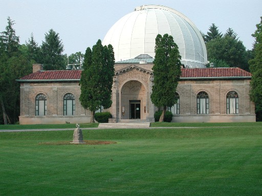
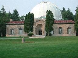
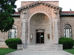
The two photos below show the Perkins Observatory Building
(photo at left) and the front door entrance to the building
(photo at right). The object on the lawn in front of the
parking lot is a sundial (photo at the left).
Perkins Observatory began in 1923 when Hiram Mills Perkins (then
90 years old) officiated at the ground breaking ceremony that
began the construction of the observatory that was to bear his name.
Unfortunately, Hiram died soon thereafter and was never to see his
project completed.
In 1861 the Civil War began. At that time, Hiram Mills Perkins was a
professor of Mathematics and Astronomy at Ohio Wesleyan University
in Delaware, Ohio. Perkins left his teaching position to join the
Union Army. The 6' 4" professor (who weighed only 97 pounds) was
rejected by the Army as unfit for service. Undaunted by this,
Hiram did the next best thing... he returned to his family's pig
farm in southern Ohio and raised hogs to help feed the Union Troops.
As a devout Methodist and a man of deep convictions, Hiram felt it
would be immoral to materially benefit from the pain and suffering
of others (even in such an indirect way as providing food for Army
troops). He therefore put his war profits into investments and
returned to Ohio Wesleyan University after the war and lived out the
rest of his life as a simple teacher.
Upon retirement in 1907, Hiram devoted himself to a new project. Over
the next 15 years he drew up the plans for an observatory to be
located in Central Ohio. Initially intended to be of modest size,
Hiram soon realized that his considerable wealth allowed construction
of a world-class facility. When it was completed in 1931, the Perkins
Telescope was the third largest in the world. Perkins Observatory had
one of the best astronomical libraries of the day, as well as facilities to
accommodate visiting astronomers from all over the world. However,
its location in central Ohio left much to be desired. For one, all
the people who live in Columbus and Delaware very rudely turn on
their lights at night. The resulting light pollution severely limited
the number of deep sky objects that could be observed. Also, the low
elevation combined with typical midwestern weather combined to make
the big telescope quite limited in usefulness. Because of this, in
1961 the Perkins Telescope was moved to Arizona, where it is now a
part of the Lowell Observatory, near Flagstaff. Perkins Observatory
has another, smaller telescope to replace it (a 32-inch, small by
professional standards but not small for amateur astronomers).
Perkins Observatory offers many programs to the public, involving
both lectures and tours of the facilities. Perkins Observatory also
has an excellent website located at:
http://www.perkins-observatory.org/
There you will find more of the history of Perkins Observatory,
details about their programs for the public, and an
excellent section about purchasing amateur telescopes, including
a set of answers to frequently asked questions (FAQs).
Directions
The following text, maps, and photos are meant to help you find
Perkins Observatory (just south of the city of Delaware, Ohio on U.S. Route
23).
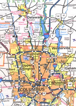 Perkins Observatory is located just off U.S. Route 23
between the cities of Columbus and Delaware, Ohio, but much closer to
Delaware. The map at the left (Map 1) is a small-size portion of a
map of Ohio showing Columbus at the bottom and the city of Delaware at
the top.
Perkins Observatory is located just off U.S. Route 23
between the cities of Columbus and Delaware, Ohio, but much closer to
Delaware. The map at the left (Map 1) is a small-size portion of a
map of Ohio showing Columbus at the bottom and the city of Delaware at
the top.
Unfortunately, in order to see what I will be referring to next, you
will
probably need to click on the image on the left to obtain a much
larger
version of Map 1, and you will probably have to go back and forth
between this text and the larger version of the map. It is relatively
easy to go back and forth in your browser, though. After you have
obtained the
large map, click the <Back> button (or equivalently, use
<Alt-left arrow>) to go back to this text. You can then click
the
<Forward> button (or equivalently, use the <Alt-right
arrow>)
to go to the large map.
On the large Map 1 locate U.S. Rte. 23 connecting Worthington (a
northern
suburb of Columbus) and Delaware. Just south of Delaware, look for the
intersection of U.S. Rte. 23 with Ohio Rte. 315 at Stratford. Follow
Rte. 23 south a short distance until you see a solid red dot; left
of that dot you will find the notation "Perkins Observatory". WARNING!! It
looks like Perkins Observatory is just off Rte. 315 but that is wrong;
Perkins Observatory is just off Rte. 23.
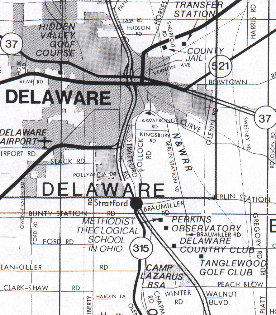
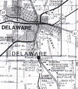 At the left is a portion of a map of Delaware County, Ohio (which
contains the city of Delaware); this is Map 2. Click on the small
version at the left to obtain a large version and use the same <Back>
and <Forward> procedure as before.
At the left is a portion of a map of Delaware County, Ohio (which
contains the city of Delaware); this is Map 2. Click on the small
version at the left to obtain a large version and use the same <Back>
and <Forward> procedure as before.
Looking at the large version of Map 2 locate the intersection of
Rte. 315 and Rte. 23 (to the right (east) of Rte. 315; Rte. 23 is shown as a
double line). Just below (south) of this intersection are shown 4 black
squares labeled in succession from north to south: (1) Methodist
Theological School in Ohio; (2) Perkins Observatory; (3) Delaware Country
Club; and (4) Tanglewood Golf Club. The new name for the Delaware Country
Club is: Dornoch Golf Club.
Perkins Observatory is south of the Methodist Theological School in Ohio
and north of Dornoch Golf Club (Delaware Country Club on the map). Although
there is a concrete barrier dividing U.S. Rte. 23, the barrier ends just south
of the entrance to Perkins Observatory, so you should have no problem being
able to turn in to the entrance to the observatory. Caution! Watch out for
oncoming northbound traffic if you are coming from Delaware. Also, watch out
for golfers and their spherical dimpled projectiles, since the entrance
to the observatory crosses the 3rd fairway of the Dornoch Golf Club, and
the golfers may not be looking at you as you drive on the road that crosses
that fairway. Also, your vehicle may receive a free wash if the sprinkler
system is turned on.
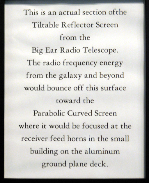
Displays About the Big Ear Radio
Telescope
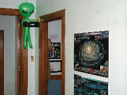 This photo shows the doorway to the room that contains
displays about radio astronomy that were created by the
staff of Perkins Observatory (in particular: Gary McCool).
There are several displays dealing with the Big Ear radio
telescope. There are also displays that deal with other aspects
of radio astronomy. See the photos below. Be aware, however, that these
displays may change from time to time; hence, the photos you see here
may not be absolutely current.
This photo shows the doorway to the room that contains
displays about radio astronomy that were created by the
staff of Perkins Observatory (in particular: Gary McCool).
There are several displays dealing with the Big Ear radio
telescope. There are also displays that deal with other aspects
of radio astronomy. See the photos below. Be aware, however, that these
displays may change from time to time; hence, the photos you see here
may not be absolutely current.
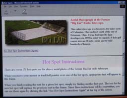
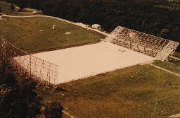 This is an aerial photo of the Big Ear radio telescope
looking northwest. Both the flat reflector (to the north)
and the paraboloidal (curved) reflector (to the south) are
aligned east-west. The flat level surface in between the
two reflectors (mirrors) is a reflecting ground plane used to
shield the telescope from the radio waves generated by the
ground underneath (which is 'hot' in the radio band compared
to the 'cold' sky).
This is an aerial photo of the Big Ear radio telescope
looking northwest. Both the flat reflector (to the north)
and the paraboloidal (curved) reflector (to the south) are
aligned east-west. The flat level surface in between the
two reflectors (mirrors) is a reflecting ground plane used to
shield the telescope from the radio waves generated by the
ground underneath (which is 'hot' in the radio band compared
to the 'cold' sky).
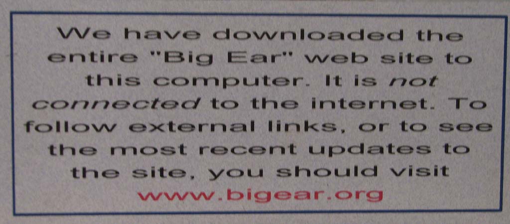
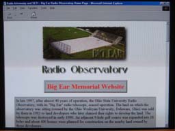
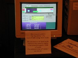
 Perkins Observatory has downloaded a copy of the Big Ear website (www.bigear.org, the website you are now visiting). The computer is not connected to the Internet so that the viewer is not able to link to external websites. [See the descrition in the photo to the left.] The leftmost photo below shows the home page of the website copy. The second photo below shows the page that identifies 7 hotspots on the aerial photo of the Big Ear radio telescope, that allows the viewer to read more about each of the main structures of the radio telescope.

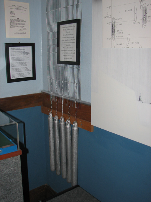
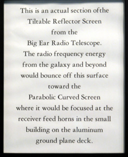 The leftmost photo shows a model of the the wire mesh and sash weights used on the Big Ear radio telescope. The second photo is a closeup of the plaque attached to this model.
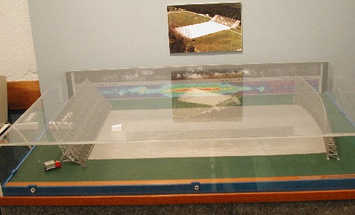
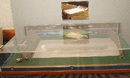 This shows a scale model of the Big Ear radio telescope
contained in a clear plastic case.
This shows a scale model of the Big Ear radio telescope
contained in a clear plastic case.
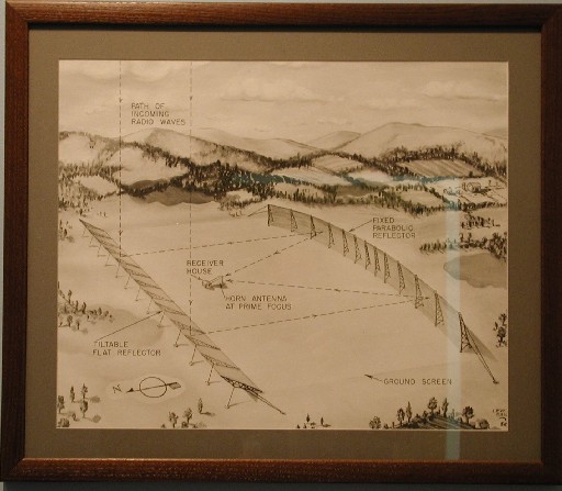
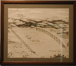 In the early days of designing the Big Ear radio telescope, its designer,
Dr. John Kraus, had planned for the reflectors to be 2000-feet
wide in the east-west direction and 200-feet high. It became
obvious that there wouldn't be enough money to build a facility
that large, so he decided to reduce the east-west dimension
to 720 feet, the height of the paraboloidal reflector to 70 feet,
and the slant height of the flat reflector to 100 feet. The
drawing in the photo to the left shows that latter design.
However, a second reduction in size had to be made when Dr.
Kraus again determined that there would not be enough money
for the 720-foot widths, so he reduced the width of the
paraboloidal reflector to 360 feet and the width of the flat
reflector to 280 feet. Thus, the "Big Ear" was constructed
with those dimensions. Construction began in 1956 and was
completed in 1961. Several years into its operation, funds
were available to widen the flat reflector from 280 feet to
340 feet.
In the early days of designing the Big Ear radio telescope, its designer,
Dr. John Kraus, had planned for the reflectors to be 2000-feet
wide in the east-west direction and 200-feet high. It became
obvious that there wouldn't be enough money to build a facility
that large, so he decided to reduce the east-west dimension
to 720 feet, the height of the paraboloidal reflector to 70 feet,
and the slant height of the flat reflector to 100 feet. The
drawing in the photo to the left shows that latter design.
However, a second reduction in size had to be made when Dr.
Kraus again determined that there would not be enough money
for the 720-foot widths, so he reduced the width of the
paraboloidal reflector to 360 feet and the width of the flat
reflector to 280 feet. Thus, the "Big Ear" was constructed
with those dimensions. Construction began in 1956 and was
completed in 1961. Several years into its operation, funds
were available to widen the flat reflector from 280 feet to
340 feet.
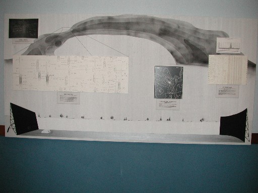
 Painted on the wall and serving as a backdrop for several
displays is a representation of how the sky would look at
a frequency of about 1420 MHz (where the Big Ear did most
of its observations). At the bottom is painted a
representation of the "Big Ear" viewing it toward the east.
Painted on the wall and serving as a backdrop for several
displays is a representation of how the sky would look at
a frequency of about 1420 MHz (where the Big Ear did most
of its observations). At the bottom is painted a
representation of the "Big Ear" viewing it toward the east.
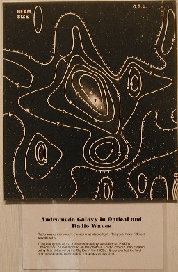 This photo shows a photograph of the Andromeda Galaxy (M31)
taken with the original 69-inch optical telescope of Perkins
Observatory overlaid with contours of radio strength of the
same area as measured at about 1420 MHz by the "Big Ear" radio
telescope. This photo got considerable worldwide attention after it was
published because it clearly showed the usefulness of
comparing optical and radio results (previously, there had been
little cooperation between optical astronomers and radio
astronomers).
This photo shows a photograph of the Andromeda Galaxy (M31)
taken with the original 69-inch optical telescope of Perkins
Observatory overlaid with contours of radio strength of the
same area as measured at about 1420 MHz by the "Big Ear" radio
telescope. This photo got considerable worldwide attention after it was
published because it clearly showed the usefulness of
comparing optical and radio results (previously, there had been
little cooperation between optical astronomers and radio
astronomers).
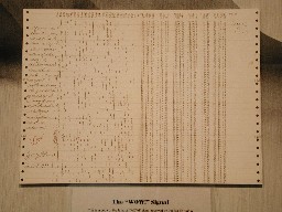
 [Caution! The large-size version
you get when you click on either this photo or the one below
is very large and will take considerable time to download under
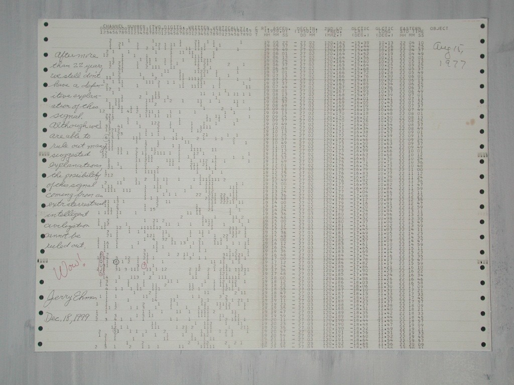
typical dialup speeds.] This photo is that of a color copy of the
computer printout of the "Wow!" signal. It shows
in red pen Jerry Ehman's handwritten exclamation of
astonishment after recognizing the importance of the
sequence '6EQUJ5' in channel 2 (shown circled, also
in red pen). At the request of Gary McCool of
Perkins Observatory, Jerry wrote a short message and
autographed this display copy. [Note. This photo was taken
with flash.]
[Caution! The large-size version
you get when you click on either this photo or the one below
is very large and will take considerable time to download under
typical dialup speeds.] This photo is that of a color copy of the
computer printout of the "Wow!" signal. It shows
in red pen Jerry Ehman's handwritten exclamation of
astonishment after recognizing the importance of the
sequence '6EQUJ5' in channel 2 (shown circled, also
in red pen). At the request of Gary McCool of
Perkins Observatory, Jerry wrote a short message and
autographed this display copy. [Note. This photo was taken
with flash.]
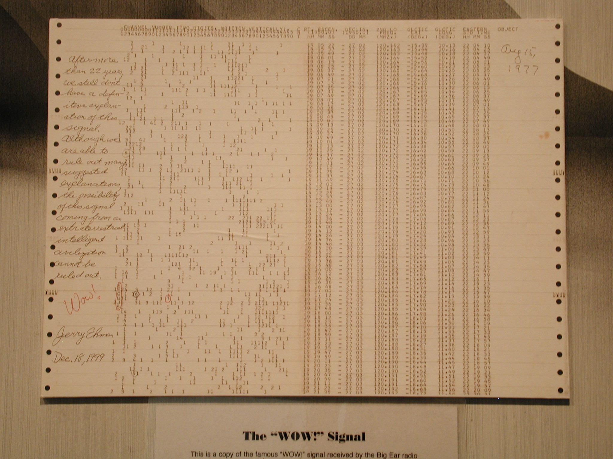
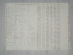
 [Note. This photo is the same as the photo above except that it was taken
without flash. The brownish color is due to the incandescent
lights in the room.] At the bottom is a portion of the caption
for this display; this caption is shown in the next photo.
[Note. This photo is the same as the photo above except that it was taken
without flash. The brownish color is due to the incandescent
lights in the room.] At the bottom is a portion of the caption
for this display; this caption is shown in the next photo.
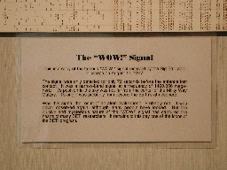 This shows the caption for the "Wow!" signal computer
printout display shown above. Originally, there was some
confusion about the date of the observation, whether it
occurred on August 15, 1977 or August 17, 1977. Later, it
was determined to be August 15, 1977 and that date was
handwritten on the computer printout in the upper right
corner. The caption here references the incorrect date.
This shows the caption for the "Wow!" signal computer
printout display shown above. Originally, there was some
confusion about the date of the observation, whether it
occurred on August 15, 1977 or August 17, 1977. Later, it
was determined to be August 15, 1977 and that date was
handwritten on the computer printout in the upper right
corner. The caption here references the incorrect date.
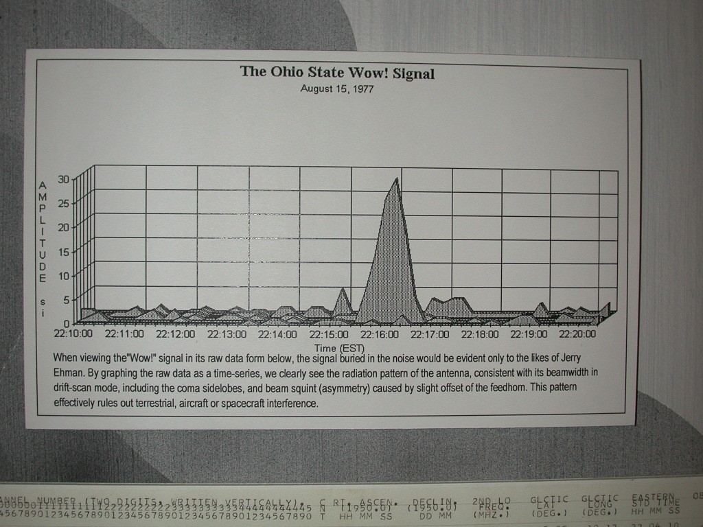
 [Caution! The large-size version
you get when you click on this photo is moderately large
and will take some time to download under typical dialup
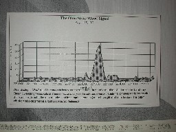
speeds.] This photo shows a graph (plot) of the
"Wow!" signal data. Time increases from left to
right, channel number (for just the first 6 channels)
increases from front to back, and signal strength,
measured in multiples of the noise background (standard
deviation of the data excluding the strong signals),
increases vertically. The "Wow!" signal is the
biggest response just right of center.
[Caution! The large-size version
you get when you click on this photo is moderately large
and will take some time to download under typical dialup
speeds.] This photo shows a graph (plot) of the
"Wow!" signal data. Time increases from left to
right, channel number (for just the first 6 channels)
increases from front to back, and signal strength,
measured in multiples of the noise background (standard
deviation of the data excluding the strong signals),
increases vertically. The "Wow!" signal is the
biggest response just right of center.
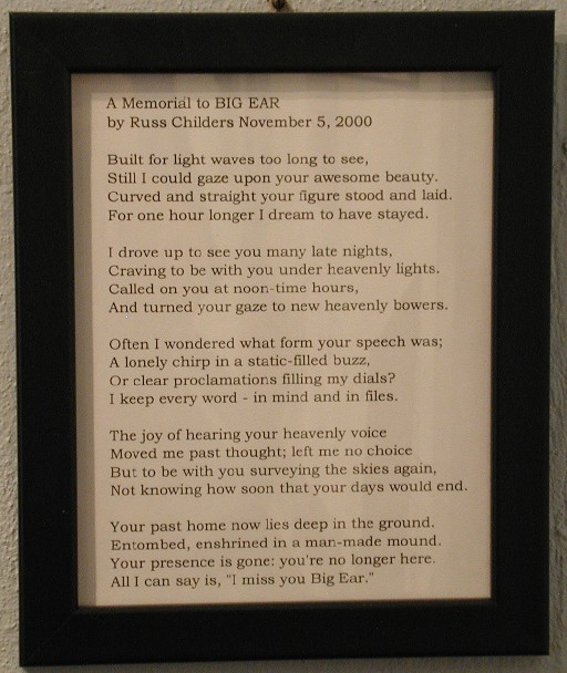
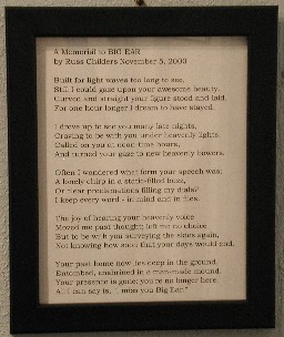 At the Ohio Historical Society/Ohio Bicentennial
Commission Big Ear Marker Dedication Ceremony held on
November 5, 2000, Russ Childers read his composition "A Memorial
to Big Ear" . It is reproduced
in the framed document shown in this photo. Russ was the
chief observer during the last years of the operation of
Big Ear. He wrote the computer programs for LOBES (LOw
Budget Extraterrestrial Survey), our narrowband sky
survey that followed up on the original narrowband survey
in which Jerry Ehman saw the "Wow!" signal.
At the Ohio Historical Society/Ohio Bicentennial
Commission Big Ear Marker Dedication Ceremony held on
November 5, 2000, Russ Childers read his composition "A Memorial
to Big Ear" . It is reproduced
in the framed document shown in this photo. Russ was the
chief observer during the last years of the operation of
Big Ear. He wrote the computer programs for LOBES (LOw
Budget Extraterrestrial Survey), our narrowband sky
survey that followed up on the original narrowband survey
in which Jerry Ehman saw the "Wow!" signal.
Other Radio Astronomy Displays and Projects
at Perkins Observatory
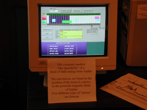
 In the same room that contains displays about the Big Ear radio telescope
are other displays dealing with radio astronomy. This photo shows a computer
monitor showing when radio bursts from Jupiter may be viewable.
In the same room that contains displays about the Big Ear radio telescope
are other displays dealing with radio astronomy. This photo shows a computer
monitor showing when radio bursts from Jupiter may be viewable.
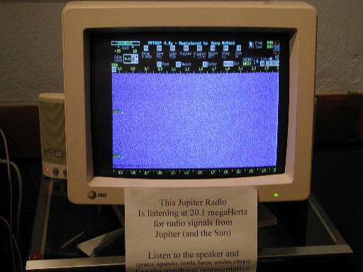
 In this photo we see a computer monitor showing the output of a receiver
connected to an antenna pointed at Jupiter. It's purpose is to display
Jupiter's bursts of radio waves in the frequencies near 20 MHz.
In this photo we see a computer monitor showing the output of a receiver
connected to an antenna pointed at Jupiter. It's purpose is to display
Jupiter's bursts of radio waves in the frequencies near 20 MHz.
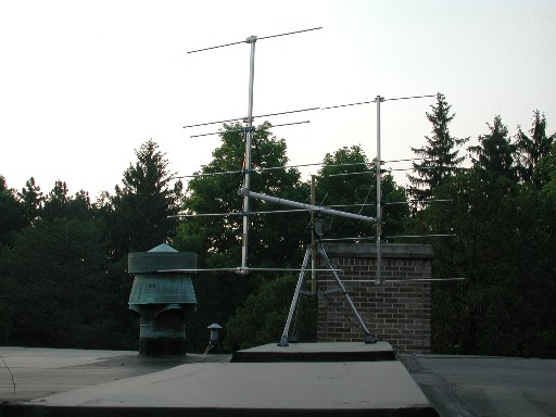
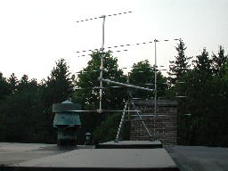 This photo shows the antenna system used to receive the radio burst signals
from Jupiter referred to above. This antenna system is a "phased array" of
two Yagi antennas. A Yagi antenna (named after the Japanese inventor) has
the property of high directivity (which means that it is quite sensitive in
one direction and quite insensitive in most other directions). A phased
array is a system in which 2 or more antennas are wired together to further
enhance the sensitivity in a certain direction.
This photo shows the antenna system used to receive the radio burst signals
from Jupiter referred to above. This antenna system is a "phased array" of
two Yagi antennas. A Yagi antenna (named after the Japanese inventor) has
the property of high directivity (which means that it is quite sensitive in
one direction and quite insensitive in most other directions). A phased
array is a system in which 2 or more antennas are wired together to further
enhance the sensitivity in a certain direction.
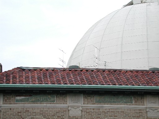
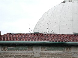 This photo shows the twin Yagi antennas used to receive radio bursts from
Jupiter. These antennas are located on the roof of Perkins Observatory, as
seen from this photo.
This photo shows the twin Yagi antennas used to receive radio bursts from
Jupiter. These antennas are located on the roof of Perkins Observatory, as
seen from this photo.
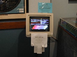 Millions of folks have downloaded the SETI@home screensaver to analyze data
taken with the 1000-foot dish located at Arecibo, Puerto Rico. Perkins
Observatory has done so also.
Millions of folks have downloaded the SETI@home screensaver to analyze data
taken with the 1000-foot dish located at Arecibo, Puerto Rico. Perkins
Observatory has done so also.
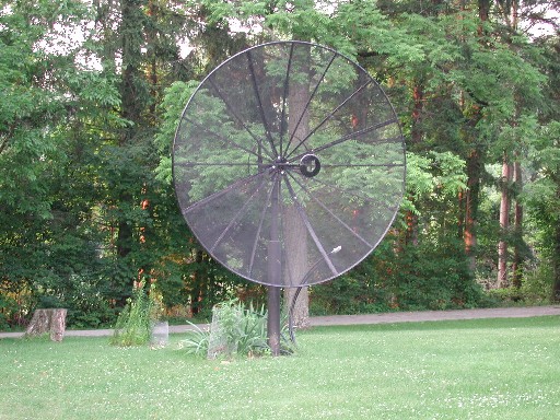
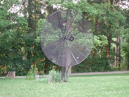 This satellite dish is the first one installed as part of an array of dishes
used as a radio telescope.
This satellite dish is the first one installed as part of an array of dishes
used as a radio telescope.
![[Aerial Photo of Big Ear]](../../bigearhp.gif)
![[NAAPO Logo]](../../NAAPOsm.jpg)